

Microstructure and interface characterization
Figure 2 illustrates the XRD patterns of the Ti–6Al–4V LPBF and substrate samples. In both samples, most peaks can be identified as the α/α′ phase. Differentiating between α and α′ is challenging since they share a hexagonal close-packed (HCP) structure and exhibit similar lattice parameters30. The observation of α peaks in the LPBF sample indicates a non-equilibrium α′ phase structure. This non-equilibrium phase structure arises due to the rapid solidification during the LPBF process, which hinders vanadium diffusion, resulting in α′ having a higher vanadium content than the α phase31. In contrast, the body-centered cubic (BCC) β-phase peaks are more noticeable in the substrate sample. However, these peaks are barely visible in the LPBF sample, potentially indicating a lower quantity of the β-phase in this particular alloy.

XRD patterns of the LPBF and substrate Ti-6Al-4V parts.
The OM images taken from the latter regions of the multi-material sample are presented in Fig. 3. Figure 3(a) shows a typical acicular α/α′ martensitic structure, as reported in the literature for LPBF Ti-6Al-4V32,33,34,35. On the contrary, the Ti-6Al-4V substrate in Fig. 3(b) exhibits nearly equiaxed grains of α and β phases, shown as light and dark regions, respectively. This metallographic microstructure, characterized by the presence of both phases, was also reported in previous studies36. As discussed earlier, the formation of acicular α′ martensite in the LPBF process instead of the equilibrium α phase found in the substrate alloy can be mainly attributed to the high cooling rates experienced by the alloy during the LPBF process, which plays a crucial role in the formation of α′ martensite from β grains in Ti-6Al-4V. In particular, the high thermal gradient within the melt pool along the building direction contributes to this phenomenon37. On the other hand, the presence of prior β grains is primarily attributed to the absence of a nucleation barrier during solidification33. An OM image of the hybrid region presented in Fig. 3(c), showing the interface between the substrate and the LPBF part with a serrated morphology left behind by the laser tracks. The absence of lack-of-fusion pores and interface cracks in the fusion zone indicates a strong metallurgical bond between the two materials at the interface.

OM images showing the microstructure of the Ti-6Al-4V multi-material part within three distinct regions (sectioned parallel to the build direction): (a) LPBF, (b) Substrate, (c) Hybrid.
The SEM images in Fig. 4(a)-(c) further, confirm that the multi-material 3D-printed part was fully dense and had no visible cracks at the interface. The contrast in surface topology between the three regions can be clearly observed, where a needle-like topology dominates in the LPBF region (Fig. 4(a)) due to the presence of the fine martensitic phase. At the same time, the substrate is comprised of a discontinuous cellular structure (Fig. 4(b)) with a clear presence of α and β phases.

SEM images showing the microstructure of the Ti-6Al-4V multi-material part within three distinct regions (sectioned parallel to the build direction): (a) LPBF, (b) Substrate, and (c) Hybrid (the dashed line represents the interface). Corresponding EDS maps of Ti (d), Al (e), and V (f) are also shown.
Based on the SEM image of the hybrid sample in Fig. 4(c), EDS analysis was carried out and the elemental maps of Ti, Al, and V are shown in Fig. 4(d)-(f). The latter images reveal a homogenous distribution of the major alloying elements, indicating the absence of elemental or macro segregation near the interface. Additionally, the EDS elemental composition was found to be consistent across the different regions of the hybrid sample (see Table 1) and matched well with the nominal composition of Ti-6Al-4V.
In addition, EBSD analyses were conducted to examine the grain characteristics and to gain further insight into the microstructural change across the interface. The inverse pole figure (IPF) maps in Fig. 5 illustrate the presence of the acicular α’ phase in the LPBF part resulting from non-diffusion martensitic transformation. The estimated volume fractions are 93% for the α phase and 7% for the β phase. There is a significant presence of fine acicular α′ martensite with high aspect ratio, which typically initiates at the prior β grain boundaries and propagates within their parent β grains. However, a few extend into the neighboring β grains. The columnar shape results from the epitaxial growth of the initial β phase, facilitated by sequential layer deposition and directional cooling along the building direction (z-direction)33. This phase contrasts the lamellar α phase observed in the Ti–6Al–4V part fabricated by the Electron Beam Melting (EBM) process, which is typical after the thermal diffusion phase transformation20,38. Moreover, in Ti–6Al–4V processed via LPBF, the α’ phase exhibits a stronger texture than the α phase observed in EBM Ti-6Al–4V20,34. EBSD measurements showed that the fusion region has a width of ~ 50 µm. Furthermore, a microstructural change across the interface is observed, with a dominance of large equiaxed grains in the substrate, smaller equiaxed grains at the interface, and an acicular α’ phase in the LPBF part.

EBSD IPF maps showing the grain distribution and orientation of the Ti-6Al-4V multi-material sample.
Figure 6(a) compares the values of surface roughness parameters, specifically the arithmetical mean surface roughness (Sa) and the maximum height (Sz), obtained for the LPBF, hybrid, and substrate Ti-6Al-4V parts prior to corrosion testing. The Sa values for all three samples were found to be similar, all falling within a range below 0.04 μm. This high similarity in average surface roughness can be attributed to the final processing step, where all samples were mechanically polished with colloidal silica (0.04 μm). However, the Sz values showed more noticeable differences among the samples. The LPBF sample exhibited the highest Sz value, followed by the substrate sample, while the hybrid sample demonstrated the lowest Sz value. This low Sz value for the hybrid sample may be attributed to partial re-melting and localized smoothing near the interface, which reduces peak-to-valley extremes compared to LPBF and substrate samples39. Sz is more sensitive to isolated surface features than Sa and may reflect the residual effects of the original manufacturing process, which means persistent surface characteristics unique to each fabrication method. In as-built LPBF samples, high Sz values arise from partially melted powder particles and staircase effects. In contrast, the substrate exhibits lower Sz values due to uniform machining marks. In the hybrid sample, intermediate remelting smooths out these extremes, resulting in the observed minimum Sz40,41. Note that unpolished parts produced by LPBF tend to have high surface roughness compared to conventionally manufactured wrought parts, mainly due to the staircase effect resulting from the layer-by-layer fabrication process42,43.

(a) Comparison of surface roughness between the LPBF, hybrid, and substrate Ti-6Al-4V samples after polishing. (b) Microhardness measurements were taken within the LPBF, hybrid, and substrate regions of the hybrid Ti-6Al-4V part.
Microhardness analysis
The microhardness of the hybrid Ti-6Al-4V part was measured within the LPBF, substrate, and hybrid regions, and the comparison of the values is illustrated in Fig. 6(b). The substrate region showed a microhardness with an average of 340.21 ± 1.29 HV, while the LPBF zone exhibited higher values with an average of 377.8 ± 3.86 HV. Interestingly, the average value at the hybrid area was 373.79 ± 9.37 HV, comparable to the microhardness of the LPBF region. The high microhardness values observed in the LPBF and hybrid regions of the multi-material Ti-6Al-4V part are attributed to its distinctive microstructure, characterized by columnar prior-β grains filled with acicular α’ martensite, contributing to its overall microhardness44.
Corrosion studies
Prior to any PDP and EIS testing, OCP tests were conducted to ensure the electrochemical stability of the exposed surfaces. In 3.5 wt.% NaCl, the stable OCP values of the substrate, hybrid, and LPBF samples were measured as −0.2436 ± 0.061 V, −0.3372 ± 0.0383 V, and − 0.2565 ± 0.0157 V, respectively. Meanwhile, in 0.5 M H2SO4, the stable OCP values of the substrate, hybrid, and LPBF samples were measured as −0.6857 ± 0.0254 V, −0.649 ± 0.0825 V, and − 0.6721 ± 0.0759 V, respectively. Figure 7 illustrates potentiodynamic polarization curves of LPBF, substrate, and hybrid Ti-6Al-4V samples in 3.5 wt.% NaCl (Fig. 7a) and 0.5 M H2SO4 (Fig. 7b). The polarization curves for all samples show similar curve shapes, suggesting they have similar corrosion mechanisms and behavior. In the NaCl solution (Fig. 7a), an initial deviation can be noticed in the PDP curves; a similar observation was reported previously for NaCl18which can be attributed to the absence of a strong passivation behavior on the surface. However, in the case of 0.5 M H2SO4 (Fig. 7b), a flade potential (EF) is evident in the anodic region around − 0.5 V, as reported in previous studies on the corrosion behavior of Ti-6Al-4V alloy in H2SO445,46. The flade potential (EF), signifies the point where a steep decrease in the current density occurs, indicating the onset of the formation of a passive oxide film at the exposed metal surface. This observation correlates with the thermodynamic behavior outlined in the Pourbaix diagram for the Ti-H2O system. Notably, the corrosion zone corresponding to the Ti²⁺ region47 matches the potential range where active dissolution occurs in strongly acidic environments. The nearly vertical line indicates full passivation of the surface, where the rate of metal ions passing through the film reaches equilibrium and becomes independent of the applied potential.

Tafel curves for the LPBF, hybrid, and substrate Ti-6Al-4V samples in (a) 3.5 wt.% NaCl (b) 0.5 M H2SO4.
Table 2 lists the values of corrosion potential (Ecorr), corrosion current density (Icorr), and corrosion rate (CR). To determine Ecorr and Icorr in NaCl, the Tafel extrapolation method was applied to the potentiodynamic polarization curve in both the anodic and cathodic regions48. These values indicate the onset of corrosive reactions on the surface of the specimens, represented by the potential and current density. The Tafel results showed that the LPBF Ti-6Al-4V sample demonstrated a high Ecorr of −0.237 ± 0.059 V and a low Icorr of 0.01426 ± 0.0066 µA.cm−2, resulting in a reduced CR. In contrast, despite achieving a comparable Ecorr value of −0.237 ± 0.120 V, the substrate sample exhibited a significantly higher Icorr of 0.03376 ± 0.017 µA.cm−2, indicating a higher corrosion rate. The hybrid sample, on the other hand, displayed a lower Ecorr value along with intermediate Icorr and CR values, positioning its corrosion performance in the PDP test between that of the LPBF and substrate samples. In the H2SO4 solution, the E-log fit was used to obtain the corrosion current density due to the presence of the ‘flade potential’ effect. Since Icorr is maintained from EF until nearly 1.3 V, the limit of the passivation region does not lie within the tested potential range. All samples exhibited poor performance in this aggressive environment, with significant corrosion degradation, in line with previous works18,49. However, the LPBF and hybrid samples demonstrated slightly improved corrosion behavior, achieving higher Ecorr and lower Icorr than the substrate sample, resulting in a lower CR for those samples.
EIS tests were conducted to examine the corrosion properties further when samples were exposed to 3.5 wt.% NaCl and 0.5 M H2SO4. In Fig. 8 Nyquist plots illustrate Z’’ (the imaginary impedance) against Z’ (the real impedance), while the Bode diagram displays dual time-constant behavior in the high-frequency to the low-frequency range. The Nyquist (Fig. 8(a)) and Bode plots (Fig. 8(b)) show the corrosion behavior in the NaCl solution, similar to what is reported in18,19while in H2SO4, Nyquist (Fig. 8(c)) and Bode (Fig. 8(d)) plots demonstrated behavior for Ti-6Al-4V samples similar to a previous report by Contu et al.50. The passive oxide films developed on Ti-based alloys typically exhibit a dual-layer structure, comprising a dense, protective inner barrier layer and a more porous outer layer51. Thus, an equivalent circuit (Fig. 8(e)) was applied to analyze the EIS data, demonstrating consistency with established research on Ti-6Al-4V and related alloys18,52, effectively capturing the dual-layer structure of the passive oxide film. This model aligns well with previous studies20,53 that have consistently identified two distinct time constants in EIS spectra, corresponding to the electrochemical processes occurring at the inner and outer layers of the passive film. This equivalent circuit comprises various electrochemical components, each representing a specific aspect of the electrochemical interface: solution resistance (Rsoln), charge transfer resistance (Rcor), double-layer capacitance (Ccor), film resistance (Rpo), and film capacitance (Cc).

Nyquist and Bode plots of the LPBF, hybrid, and substrate Ti-6Al-4V: (a)-(b) 3.5 wt.% NaCl, (c)-(d) 0.5 M H2SO4, (e) Fitting circuit.
Table 3 summarizes the electrochemical properties derived from the EIS data. In the NaCl solution, the LPBF and hybrid samples achieved comparable Rcor values, higher than those of the substrate, which agrees with the Tafel results. In contrast, in H2SO4, the Rcor values of the LPBF and hybrid samples were lower than those of the substrate, differing from the trends observed in the PDP tests, yet still in the range of the EIS results reported in49. This slight discrepancy may be influenced by sample preparation, which may cause minor differences in the exposed surface’s chemical composition and grain morphology. In NaCl solution, localized pitting corrosion tends to dominate. Conventional machined Ti-6Al-4V substrates often contain alpha-beta phase boundaries and inclusions that act as pitting initiation sites in the presence of chlorides, leading to reduced corrosion resistance54. In contrast, in acidic environments such as H2SO4, corrosion is more uniform and governed by passivity breakdown across the entire surface. Here, the homogeneous, strain-hardened microstructure of the substrate promotes the formation of a stable, protective TiO2 film, resulting in higher impedance and superior resistance compared to LPBF and hybrid samples, which are more prone to film defects due to surface porosity and elemental segregation55. Overall, the values attained from the EIS test showed relative consistency with potentiodynamic polarization test results.
Surface chemistry is crucial in defining a material’s surface properties56, where minor variations in composition can significantly impact corrosion resistance. Based on the XRD analysis in Fig. 2, a dominating presence of HCP peaks, representing the α-phase, is observed in the LPBF sample. Conversely, a higher relative intensity of the β-phase is observed in the substrate sample. This is also confirmed by the relatively higher Al content in the LPBF sample and the relatively higher V content in the substrate sample obtained through EDS mapping (see Table 1). Microstructure and metallographic analysis results reveal that the LPBF and hybrid samples both primarily comprise α’-Ti, with a secondary presence of β-Ti phases, which form due to the steep temperature gradients involved in the LPBF process. This metastable martensitic α’-Ti phase in LPBF parts is often associated with a higher thermodynamic energy state due to the finer microstructure, higher grain boundary density, non-uniform element solidification, and process-induced residual thermal stresses8,57. This makes the α’ phase more reactive in corrosive environments, where it has generally shown a greater susceptibility to electrochemical degradation compared to conventionally manufactured Ti-6Al-4V components with an equilibrium α + β microstructure. Grain boundaries contain defects such as dislocations, vacancies, and irregular lattice structures57where the non-uniform elemental composition and atomic-scale segregation along these boundaries further promote localized corrosion58,59.
In this study, other factors seem to have played a more significant role in enhancing the corrosion resistance of LPBF parts60,61,62. One of those factors is the thickness and stability of the surface oxide layer, which is a key factor influencing corrosion resistance. The higher reactivity of the α’ phase induced a more rapid formation of the protective oxide layer in LPBF than in the substrate. This effect was also observed by Lu et al.63, where a laser surface treatment of Ti-6Al-4V samples induced the formation of a martensitic α’ microstructure on the surface, which was found to improve corrosion resistance against chloride-induced pitting. This effect was attributed to the improved stability and uniformity of the protective oxide layer. In contrast, the coarser microstructure in the substrate may result in a less uniform passive layer (TiO2-film) production, making conventional machined Ti-6Al-4V alloys more susceptible to corrosion in NaCl solution compared to the hybrid and LPBF Ti-6Al-4V alloys63,64. Although roughness is often a major factor affecting corrosion resistance, this investigation eliminated its impact, as all samples were polished to the same roughness. As seen from Tables 2 and 3, the H2SO4 electrolyte is extremely harsh for LPBF, hybrid, and substrate Ti–6Al–4V samples, causing severe corrosion damage regardless of the processing method. However, the hybrid sample demonstrated corrosion performance comparable to individual materials. A passive layer forms on the surface, primarily composed of TiO2, with aluminum and vanadium oxides concentrated in the α and β phases, respectively65. Vanadium oxide increases the corrosion rate by creating vacancies that facilitate ion penetration. Moreover, the oxidation of H2SO4 leads to the formation of titanium hydrides, which are known to cause damage66. As a result, (SO4)2− ions increase electric defects in the passive TiO2 layer, making it more porous67,68. This is because stable Ti ion complexes with (SO4)2− ions facilitate the dissolution of the film. Furthermore, dissolved titanium hydrides prevent the trigger formation of a new oxide layer for re-passivation. Thus, hydride-induced defects significantly reduce ductility and cause cracking in the sample66,67,68.
Following the electrochemical tests in 3.5 wt.% NaCl and 0.5 M H2SO4, SEM images of the corroded surface of the Ti-6Al-4V LPBF, hybrid, and substrate alloy were captured, as displayed in Fig. 9. It is important to note that the potential range did not reach the typical pitting potential for Ti-6Al-4V in Fig. 7(a). Therefore, classical pitting corrosion was not expected under these conditions. Some isolated surface features could be observed post-test, which may be related to process-induced defects (e.g., lack-of-fusion voids) or corrosion-induced attack sites rather than true electrochemical pitting, as displayed in Fig. 9(a)-(c). However, these AM defects were not visible prior to corrosion testing, making differentiation challenging.
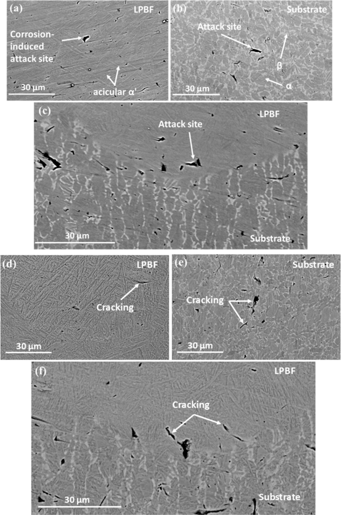
SEM images of LPBF, Substrate, and Hybrid Ti-6Al-4V samples captured after the corrosion test (a)-(c) in 3.5 wt.% NaCl (Surface features include corrosion-induced attack sites and AM-related defects), (d)-(f) in 0.5 M H2SO4.
EDS analysis was performed on the corrosion pits shown in Fig. 9(a, b) for both LPBF and substrate samples after exposure to 3.5 wt.% NaCl solution. The results revealed a presence of Oxygen (O) within these corrosion pits in both substrate (5.806 wt.%) and LPBF (2.008 wt.%) samples; as expected, the deterioration of the oxide layer due to chemical reactions initiated by Cl− ions65 leads to the rapid diffusion of those ions from the passive layer, followed by pores and the dissolution of Ti-6Al-4V samples. Moreover, the corrosion-induced attack sites formation resulting from the high corrosion rate could be attributed to the accelerated degradation of the TiO2 layer by hydrogen-induced defects69. In H2SO4, crack-like defects can be observed in all samples, as shown in Fig. 9(d)-(f). However, in both solutions, the breakdown of passive films tends to occur in the grain boundaries rather than the interior of grains, particularly in the substrate alloy, as observed in SEM images where corrosion defects are predominantly concentrated around the β-phase regions. This indicates a susceptibility of the β-phase to localized corrosion, potentially due to a less stable oxide layer over the β-phase grains.
3 Comments
https://shorturl.fm/v9K1k
https://shorturl.fm/l6XUz
https://shorturl.fm/bszvY